Object
To make hydrogel beads and  spider-web hydrogel
In this research, we used two types of microdevices to control the shape of DNA hydrogel. One was used for DNA hydrogel beads, the other was for a spider-web shaped DNA hydrogel.
DNA hydrogel beads were used for evaluation of swelling and shrinking ratio of DNA hydrogel, because beads are well uniformed and sizes are well monodisperse, so we can analyze the ratio easily.

Therefore, we used microdevice, which enable to control the size and shape of DNA hydrogel.
Our goal is to generate a DNA spider net, which can swell or shrink . To achieve this, we designed mold microdevice of DNA hydrogel whose channel draws the shape of DNA spider net.
Ex 2-1 DNA hydrogel beads generation
Overall picture of gel beads generation is shown in Figure 2-1.
First, we prepared two tubes of solution with materials of DNA hydrogel, one containing st1 + st3 +l1 and the other, containing st2 + st4 +l1 respectively. These tubes were connected to pressure pump and were injected into the microdevice with two different nozuls.
At the junction where place they solutions and oil encounter, oil and surfactant was mixed, then droplet containing DNA hydrogel component(st1~st4 + l1) was generated. For a while, in the droplet, DNA hydrogel was formed and its shape became sphere.

Figure 2-1 A microdevice for generation of DNA hydrogel beads

Ex2-2 A spider-web DNA hydrogel
In order to generate spider shaped DNA hydrogel, we designed microdevice.
Basic mechanism was the same as above, but oil was not needed.
Separated solutions were injected from inlets located top of the devices.with heat because gelification in a way can cause clogging(DNA hydrogel was melt in high temperature).
At the moment when all the way was filled with solution, the system was cooled, then  spider-web shaped DNA hydrogel was formed.
The channel was drawn as below(Figure 2-2). Branched way may produce air bubbles, therefore, the spider-web was drawn with one-stroke.

Figure 2-2 Spider-web channel

Protocol
Basic protocol of making microdevice is common with a device for beads and that for spider-web(Figure 2-2).

1. Silicon Wafer(5 inch in diameter) was dried in oven at 200℃ for 2 hour(to remove water in surface).
    Then, the wafer was coated by SU8 2050, 8 g.
     After the surface was flattened, the wafer was baked at 65 ℃ for 1 min and then 95℃ for 9 min.
2. The wafer was covered with channel printed film and exposed to UV  for 25 seconds.
     Where UV was radiated  became crosslinked.
3. We removed the film from wafer and baked the wafer was baked at 65 ℃ for 1.5 min and then 95℃ for 7 min.
4. To remove where UV was not radiated, the surface was developed by SU8 developer. 
    After that, it was washed by iso-propanol.To protect the surface, it was coated by fluorene.
5. PDMS was put on the wafer, and baked at 75℃ for 1 hour.
6. To stick the PDMS and a glass slide, they were exposed by oxygen plasma, 
    which cause their surface coated with OH groups, then they were sticked to each other.

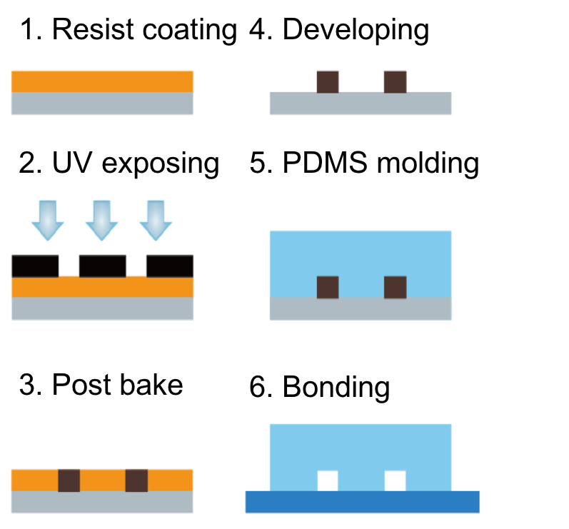
Figure 2-3 How to make a microdevice

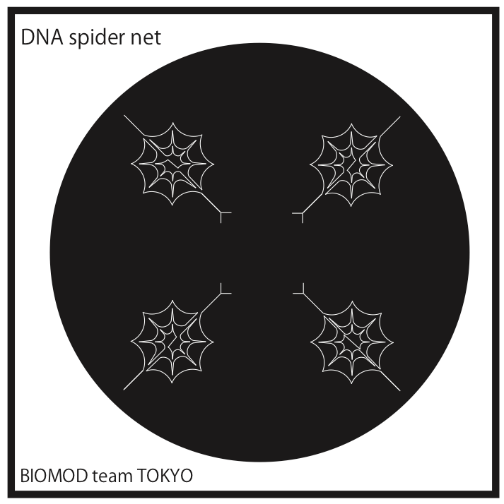
Figure 2-4 Spider-web printed channel film.

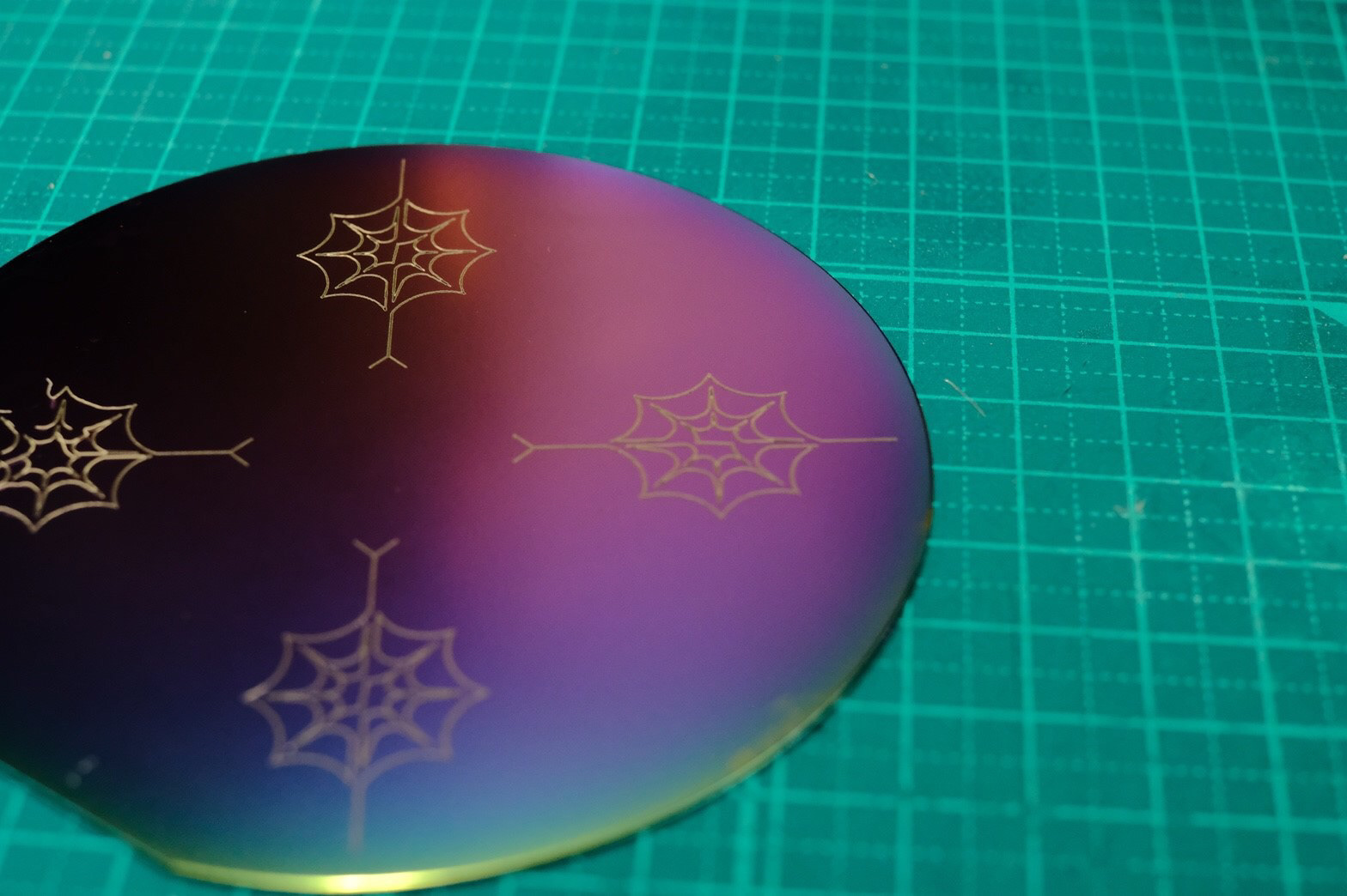
Figure 2-5 Spider-web printed silicon wafer  

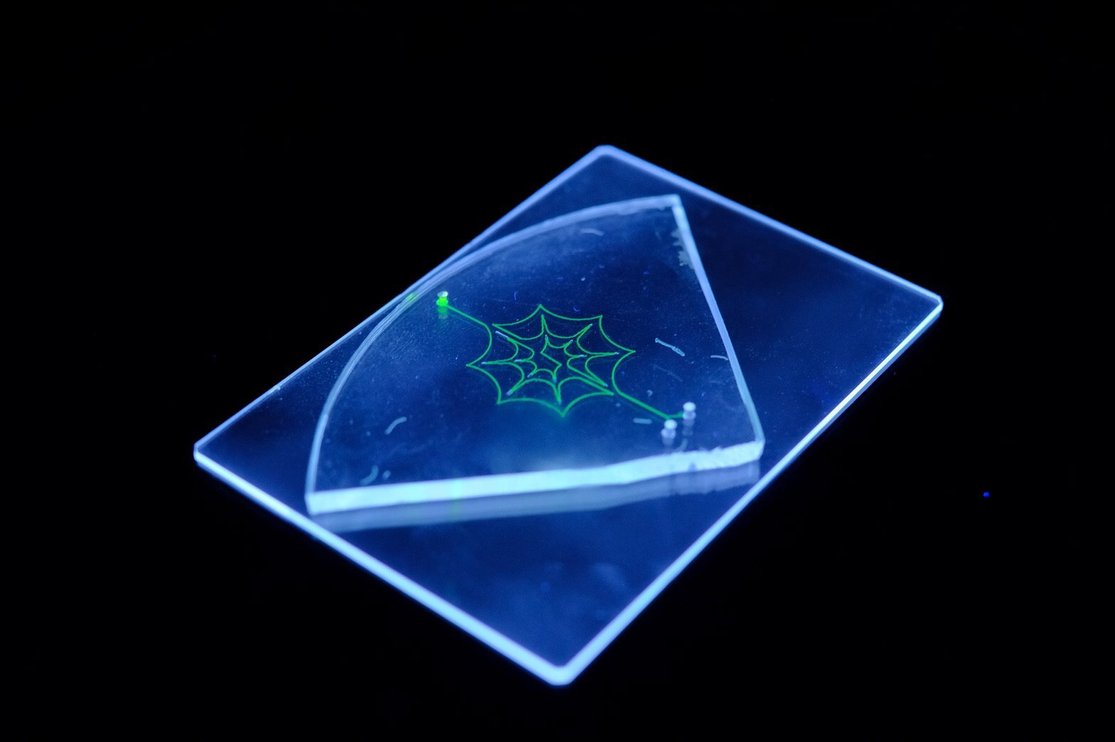
Figure 2-6 A Spider-web DNA microdevice.

The green fluorescence is fluorescein radiated by UV, not DNA hydrogel.

Ex 2-1 DNA hydrogel beads generation
Below solutions were prepared to generate DNA hydrogel beads.
For detection of st1 FAM was added.
Ex2-2 A spider-web DNA hydrogel​​​​​​​
Below solutions were prepared to generate spider-web DNA hydrogel. To check that component 1 and component 2 are added equally, st1 FAM and cascade blue were added. Not let the solution gelified in a halfway of the channel, the spider-web microdevice was put on a hotplate 60℃.

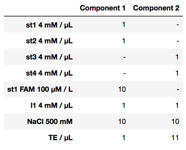
*Strand l1 was not contained because the destination of ex2-2 was to make spider-web DNA hydrogel, not to make it swell or shrink.

Result

Ex 2-1 DNA hydrogel beads generation
In Figure2-7, we show the movie of generation of DNA hydrogel. Uniform sphere DNA hydrogels were produced.  The diameters of gels were around 40 µm.

Figure 2-7 Junction of DNA hydrogel components and oil

While water solutions flow from right to left,oil came from top and bottom of images and sandwitched water solution.

Figure 2-8 Generated DNA hydrogel beads

Ex2-2 A spider-web DNA hydrogel
When solutions, component 1 and component 2  were added, injecting them equally was so difficult that they were not mixed in the channel. One time, only component 1 was injected, and another time, vise versa. That is because the resistance of the channel is different for each inlets. Therefore, we mixed component 1, 2 in advance, and heated not to let them gelify. Then, the mixed solution was injected the spider-web channel.

From the the fluorescence, component 1(st1, st3) and component 2(st3, st4) were mixed and injected into the channel. However, the solution was not gelified but just like solution. Usually, when DNA hydrogel was formed, the liquid including DNA represents ununiform fluorescence. On contrast, in the spider-web channel, there was only uniform solution. Therefore, it is difficult to say DNA hydrogel was formed.

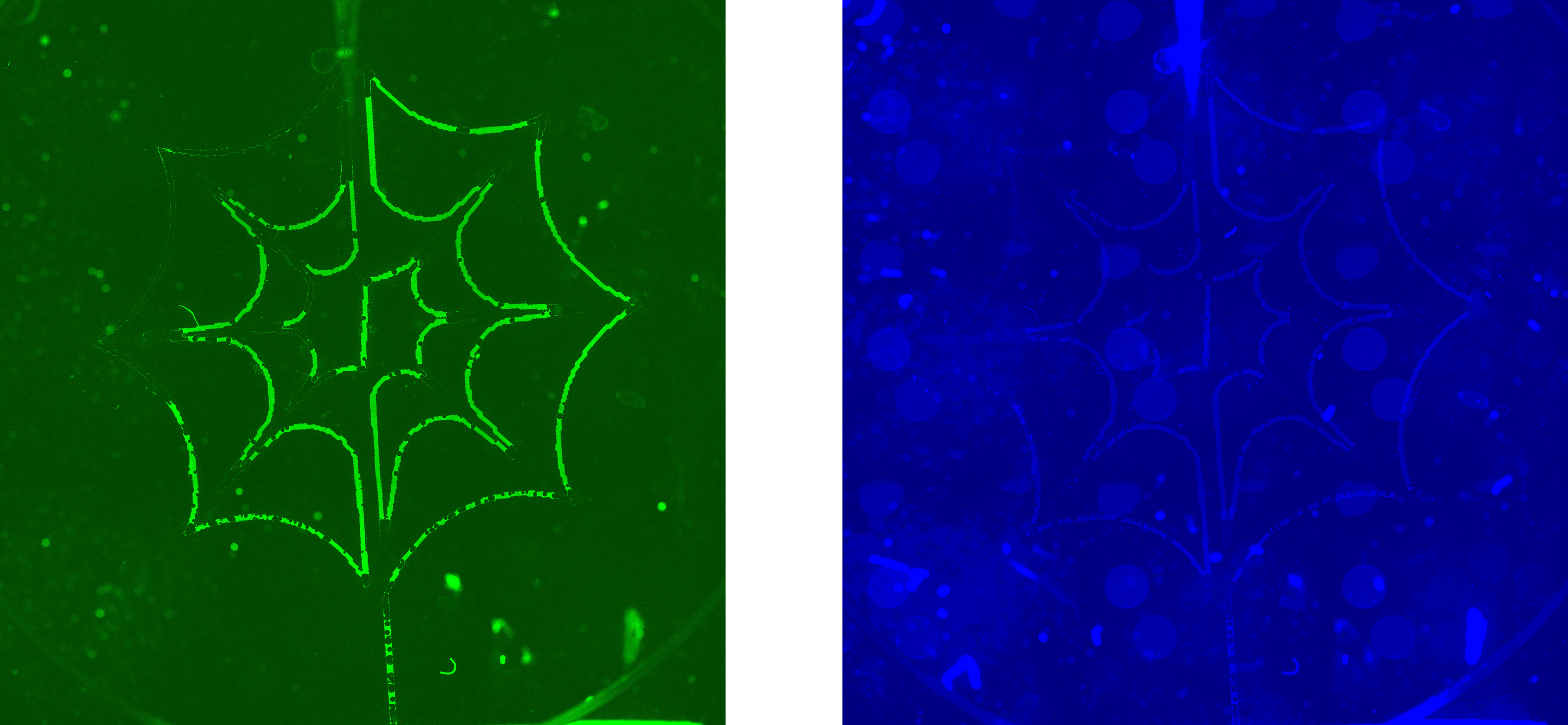
Figure 2-9 (Left) The spider-web channel observed by fitc. (Right) The same spider-web channel observed by cascade blue.

Their distributions were almost same. This means they are mixed well.

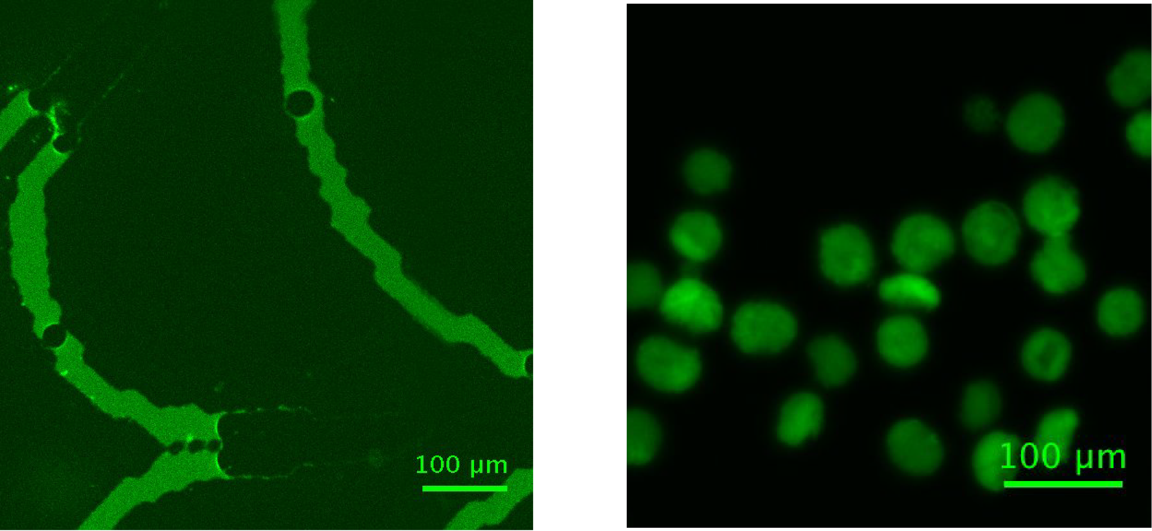
Figure 2-10 (Left) Magnified image of above spider-web channel. (Right) DNA hydrogel beads


Discussion

Ex 2-1 DNA hydrogel beads generation
With droplet microfluidics devices, we generated DNA hydorogel beads which can keep its shape in TNE buffer. DNA hydrogel beads with uniform diameter could be synthesized well. These beads were used for evaluation of swelling and shrinking in Experiment 3 and Experiment 4.

Ex2-2 A spider-web DNA hydrogel
Spider-web DNA hydrogel was not generated.
When the same solutions were mixed on a glass plate, they gelified well(no data).
Therefore, the difference was only that they were mixed in spider-web channel or not.

One of the reason is that bubbles in a channel interfered the formation of DNA hydrogel.
There were many bubbles in a channel(Figure 2-11), these bubbles may prevent the formation of DNA hydrogels.

Figure 2-11. Bubbles in a channel

Another reason is a kind of manipulation mistakes. When solutions(one containing component 1, the ohter containing component 2) were mixed, they were gelified, and the gel sticked to the surface of equipments. Only remained solution with low concentration went through the channel. As a result, DNA hydrogel was not formed because the concentration of component 1, 2 was low.
However, these are just hypotheses. Further experiments are needed.
Back to Top